|
DeWALT 20V MAX Power Tools Battery Interface
Cross-Reference
DeWALT 20V MAX Battery Pin-Out
Note that as reported in "DeWalt 20V Max 3.0Ah Battery Pack Teardown & Analysis" (see "Related Links" section below), "The battery is always connected to the terminals. There is no way that the BMS can cut off current if the pack voltage is low. It's up to the tool to determine the cutoff point and refuse to work below that." DeWALT 20V MAX Power Tool Pin-OutThe following photo shows the interface pins on the DEWALT DCF911B 20V MAX 1/2" Impact Wrench. Cross referencing it with the battery interface in the previous section, we can see that the power tool interfaces to the TH pin and the C3 pin. In order to figure out how the tool operates with the battery, we ripped up a piece of paper to cover the two middle pins. We determined that the DeWALT 20V MAX power tools will not operate without either or both of the middle pin. So if you want to interface to the DeWALT 20V MAX power tool with other battery source, you'll have to fake out the two middle pins. The question is how to fake it out?
Cross-Reference
Off-Brand Power Tools for DeWALT 20V MAX BatteriesThere are many off-brand power tools on the market that uses DeWALT 20V MAX battery packs. We happen to have two of them:
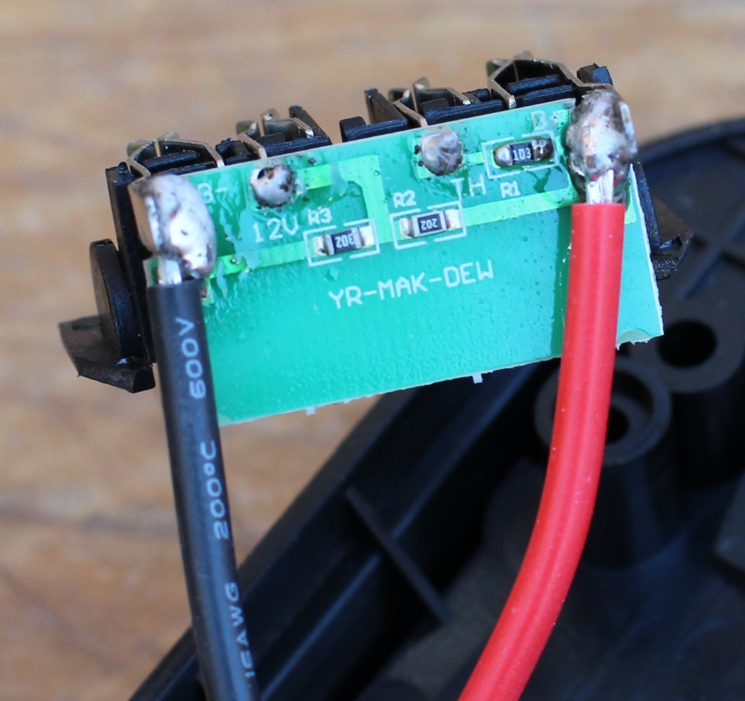
All these off-brand power tools have the same four pins as the DEWALT DCF911B 20V MAX 1/2" Impact Wrench. But will these off-brand tools work with the middle pin(s) masked out? We did the same masking test as we did on the DEWALT DCF911B 20V MAX 1/2" Impact Wrench. And the result is that both off-brand power tools worked even when either of the two middle pins are masked out. So the bad news is that these power tools will not utilize the intelligence of the DeWALT battery pack. But the good news is that you can build straight-through battery adapters for them. Inside of a Battery AdapterTo answer the question from the previous section, we purchased the Milwaukee M18 RedLithium Battery Pack to DeWALT 20V MAX Power Tool Adapter on Amazon. Then we took it apart to see what's inside. Inside the adapter, there is a very simple surface-mount circuit board (see photo below). It consists of three surface-mount resistors--103, 202, and 302--that ties the power and ground to the two inner pins. The B+ pin is tied to the TH pin with a 103 resistor. The B+ pin is tied to the C3 pin with a 202 resistor. The B- pin is tied to the C3 pin with a 302 resistor. And finally, the 202 resistor and the 302 resistor are wired in series between the B+ pin and the B- pin. 
Using the Online calculator - 3 digit SMD resistor, we determine that the resistors values are as follows:
Note that the adapter uses 16 gauge wires (see photo above). So if you are to wire up your own battery source, you'll probably want to use 16 gauge wires as the minimum thickness. Related Links
Attachments
|
Articles
|
Wiki
227 Users Online
|
|
Copyright © 2004 - 2025. All Rights Reserved. |